

close
Choose Your Site
Global
Social Media
Views: 0 Author: Site Editor Publish Time: 2026-08-24 Origin: Site


Bedside urine drainage failures—specifically leaks, flow obstructions, and valve malfunctions—are frequently attributed to user error, but root-cause analyses consistently point to micro-misalignments during the manufacturing process. For medical device manufacturers, imprecise outlet tube insertion leads to high scrap rates, failed pressure tests, and severe compliance risks. Relying on manual alignment or legacy equipment introduces unacceptable variances in high-volume production.
Achieving zero-defect manufacturing requires transitioning from manual positioning to automated, sensor-driven alignment. This guide evaluates how a modern Drainage Bag Making Machine controls outlet tube alignment, the technical mechanisms involved, and how to assess equipment for reliable, compliant production.
Precision Dictates Performance: A deviation of even 1-2 millimeters in outlet tube alignment can compromise the weld integrity, leading to micro-leaks or flow restriction at the valve connection.
Automation Replaces Guesswork: Advanced production lines utilize servo-driven indexing, robotic grippers, and optical vision systems to guarantee exact tube placement before and during the welding phase.
Welding Technology is Critical: High-frequency (HF) welding must be perfectly synchronized with the alignment module to prevent thermal shifting of PVC or TPU materials.
Compliance Requires Traceability: Evaluating a machine requires looking beyond speed; in-line quality control and automated rejection systems are mandatory for ISO 13485 compliance.
Poor alignment during manufacturing has a direct clinical impact on patient safety and comfort. When an outlet tube is inserted with even slight deviation, it creates uneven tubing tension across the bag. This tension restricts fluid flow and makes it difficult for healthcare providers to properly attach or operate drainage taps and valves. Severe patient complaints often stem from these manufacturing defects, particularly night-time bedside leaks, fluid pooling, and flow obstructions. Stagnant urine caused by a blocked or kinked tube significantly increases the risk of subsequent bladder infections.
The weld must also withstand the mechanical stress of daily use. Patients and nurses apply rotational torque and pulling forces when repeatedly unscrewing threaded caps, such as blue outlet caps, or attaching syringes for washout procedures. Achieving a 360-degree hermetic seal around the outlet tube without deforming the tube's inner diameter or compromising the bag's structural integrity is the primary success criterion for manufacturers. Any weakness in this seal will eventually fail under clinical conditions.
To understand the mechanical forces at play, consider the daily routine in a clinical setting. A nurse might empty a drainage bag four to six times a shift. Each interaction involves pulling the bag, twisting the valve, and sometimes clamping the tube. If the outlet tube was misaligned by just 1.5 millimeters during production, the high-frequency weld will have a thin spot on one side and a thick spot on the other. The thin spot acts as a stress concentrator. Over a 48-hour period of clinical use, the repeated torque from operating the valve will cause that thin spot to fatigue, resulting in a micro-leak. This is why visual inspections are insufficient; the alignment must be mechanically perfect before the weld is even struck.
Medical-grade PVC, EVA, and TPU exhibit distinct thermal dynamics during manufacturing. When heat and pressure are applied to form a seal, these polymers soften and flow. This phase transition introduces a high risk of material shifting or shrinking. If the outlet tube is not held rigidly in place, the melting film can push the tube off-center.
Legacy equipment often fails to compensate for this material deformation. Without dynamic pressure control and precise tooling, the resulting welded joints feature skewed outlet tubes. These misaligned tubes exacerbate tubing tension during patient use, leading to premature failure of the drainage system. Modern systems account for the specific melt flow index of the chosen material, applying exact thermal profiles to ensure the film bonds uniformly around the tube without displacing it.
Different materials require entirely different handling strategies on the factory floor. PVC, for instance, responds exceptionally well to dielectric heating because of its high dielectric loss factor. However, it is prone to thermal degradation if the weld cycle is too long. TPU, on the other hand, requires much tighter temperature controls because its transition from solid to liquid is abrupt. If the alignment tooling does not account for the rapid melt phase of TPU, the tube will slip out of position the moment the high-frequency power is applied.
Material Type | Thermal Behavior During Welding | Alignment Risk Factor | Required Machine Compensation |
|---|---|---|---|
Medical-Grade PVC | Gradual softening, high dielectric response | Moderate shifting under pressure | Standard internal mandrels, controlled HF power ramping |
Thermoplastic Polyurethane (TPU) | Rapid phase transition, highly fluid melt | High risk of tube slippage | Precision servo-grippers, rapid cooling cycles under pressure |
Ethylene Vinyl Acetate (EVA) | Low melting point, sticky when heated | Adhesion to tooling, deformation | Teflon-coated dies, strict temperature regulation |
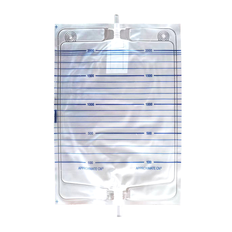
The alignment process begins long before the welding press engages. Vibratory bowl feeders and linear tracks are utilized to orient outlet tubes, valves, and specialized connectors. These feeding systems ensure that every component arrives at the insertion station in the exact same orientation. Once positioned, multi-axis robotic grippers and servo-driven indexing mechanisms take over. They place the tube precisely between the upper and lower film layers.
To maintain the structural integrity of the tube during this high-speed transfer, mechanical centering guides and internal mandrels are deployed. The mandrel slides inside the tube, holding its internal structure rigid during placement and welding. This guarantees the lumen remains fully open, preventing future flow blockages that could harm patients.
The mechanics of the vibratory bowl feeder are highly specialized. The bowl is tuned to a specific frequency that causes the plastic tubes to "walk" up a spiral track. Tooling along the track physically rejects tubes that are upside down or damaged, dropping them back into the center of the bowl. By the time a tube reaches the linear outfeed, it is perfectly oriented for the robotic gripper. The gripper itself uses pneumatic actuation to grab the tube without crushing it, relying on proximity sensors to confirm it has a solid hold before moving it to the welding station.
Bulk tubes are loaded into the vibratory hopper.
Tubes are oriented and fed down a linear track.
A pneumatic separator isolates a single tube at the end of the track.
The servo-driven gripper retrieves the tube.
The gripper positions the tube exactly 15mm between the two layers of medical film.
The internal mandrel extends into the tube to provide structural support.
The welding press descends to lock the assembly in place.
Perfect alignment relies on flawless synchronization between the tube insertion module and the medical bag welding machine. Whether utilizing high-frequency (HF) or heat-contact welding, the press must engage at the exact millisecond the tube is secured. Custom-machined welding dies, often referred to as tooling, are designed with specific cavities to cradle the tube. These cavities prevent any lateral movement during the weld cycle.
Pressure distribution controls are integrated into the welding press to ensure an even melt flow around the tube. If the pressure is too high, the tube will crush; if too low, the seal will leak. The custom tooling ensures the joint cures with enough structural strength to withstand high-torque end-user interactions.
The design of the welding die is a masterclass in precision machining. The upper and lower dies must mate perfectly around the cylindrical shape of the tube while simultaneously pressing flat against the surrounding film. To achieve this, the dies feature a contoured pocket. When the press closes, this pocket surrounds the tube, leaving a microscopic gap for the melting plastic to flow into. This flow creates a reinforced collar of plastic around the base of the tube, significantly increasing the tear strength of the final product. If the tube is misaligned by even a fraction of a millimeter, the die will pinch the tube wall, creating a weak point that will fail during burst testing.
High-speed cameras and photoelectric sensors are implemented to verify tube position prior to welding. These optical systems scan the insertion zone, measuring the tube's placement against strict digital tolerances. Closed-loop feedback systems process this data in real-time. If a tube is detected outside the acceptable tolerance threshold, the machine automatically halts or adjusts the positioning before the weld occurs, saving raw materials.
Optical inspection continues post-weld. Cameras identify flash, burns, or incomplete seals immediately after the press releases. This continuous monitoring ensures that defective units are flagged and removed from the line long before they reach the packaging stage.
Modern vision systems use edge-detection algorithms to calculate the exact center line of the tube relative to the edges of the film. The camera captures an image in milliseconds, and the industrial PC processes the contrast between the opaque tube and the transparent film. If the center line deviates beyond the programmed limit—usually 0.5mm—the PLC triggers an immediate fault. This prevents the machine from wasting energy and materials on a bag that is guaranteed to fail quality control. Furthermore, post-weld cameras look for "weld flash," which is excess plastic that has squeezed out of the die. Excessive flash indicates that the pressure was too high or the tube was slightly oversized, both of which require immediate operator intervention.
When selecting a urine bag production line, manufacturers must analyze the conceptual trade-off between machine speed and alignment accuracy. Faster indexing requires more robust vibration dampening to prevent tube shifting during high-speed transfers. If the machine cycles too quickly without adequate stabilization, the reject rate will spike due to misaligned welds.
Evaluating cycle times involves looking at the dwell time needed for precise alignment and welding. Dual-lane or multi-station rotary systems offer a solution to this bottleneck. By processing multiple bags simultaneously, these systems maintain high throughput (bags per minute) without sacrificing the critical dwell time required for perfect tube insertion and HF curing.
Consider the physics of moving a web of plastic film. When the servo motor pulls the film forward to the next station, it creates a wave of tension. If the machine indexes too fast, this tension wave can literally snap the tube out of the gripper's hold just before the welding die descends. To counteract this, high-end machines use dancer rollers and tension control load cells to smooth out the web movement. They also utilize heavy cast-iron frames to absorb the kinetic energy of the moving press, ensuring that vibrations do not travel through the chassis and disrupt the alignment of the components.
A versatile production line must handle various outlet configurations, including standard T-taps, push-pull valves, lever taps, threaded blue outlet caps, and specialized ENFit connectors. Assess the equipment's ability to adapt to these different components. The complexity of tooling changeovers directly impacts factory uptime.
Quick-release molds offer significant advantages over traditional bolted fixtures. Modularity is essential for manufacturers producing multiple SKUs on a single line. Fast, repeatable changeovers ensure that alignment tolerances remain tight even after switching from a standard drainage bag to a specialized pediatric unit.
A poorly designed changeover process introduces massive risks for alignment errors. If a technician has to manually calibrate the depth of the insertion mandrel using hand tools and a ruler, the process is inherently flawed. Advanced equipment utilizes RFID-tagged tooling. When the operator installs a new welding die and gripper set, the machine reads the RFID tags and automatically loads the correct servo positions, HF power settings, and vision system tolerances from its database. This eliminates human error and ensures that the first bag off the line after a changeover is just as perfectly aligned as the last bag from the previous run.
Alignment technologies developed for drainage bags translate effectively to other medical fluid bags, such as IV bags, enteral feeding bags, and ostomy bags. Investing in a versatile liquid bag making machine capable of handling different tube diameters, connector types, and materials yields a higher return on investment.
A robust architecture allows facilities to pivot production based on market demands with minimal retrofitting. The core principles of servo-driven alignment, internal mandrels, and optical verification remain consistent across all flexible medical fluid containers.
For example, an enteral feeding bag requires a much larger diameter outlet tube to handle viscous nutritional formulas. The alignment system must be robust enough to handle the increased weight and rigidity of this larger tube. If the machine was built with modularity in mind, upgrading the vibratory bowl and swapping the gripper jaws takes less than an hour. The underlying logic—using a mandrel to prevent crushing and a vision system to verify placement—remains exactly the same. This cross-platform capability is what separates a single-purpose machine from a true manufacturing asset.
Automated pneumatic leak testing stations are integrated immediately following the welding process on a modern drainage bag production line. The machine isolates and tests the outlet tube weld specifically. It applies standardized burst pressure parameters to simulate the stress of a full bag and the tubing tension experienced during clinical use.
Automated rejection mechanisms physically separate defective units from the yield without operator intervention. If a micro-leak is detected around the outlet tube, the system diverts the bag to a scrap bin. This guarantees that only fully validated, hermetically sealed bags proceed to sterilization and packaging.
The mechanics of in-line leak testing are highly precise. The machine clamps down on the bag, sealing the perimeter, and injects compressed air through the outlet tube. A highly sensitive pressure decay transducer monitors the internal pressure for a fraction of a second. If the pressure drops by even 0.01 PSI, it indicates a micro-leak. The system is so sensitive that it must compensate for ambient temperature changes in the factory, as warmer air expands and can throw off the pressure readings. Bags that pass this rigorous test are stamped with a batch code, while failures are immediately dropped through a trapdoor into a locked reject bin, preventing them from accidentally being mixed with good product.
Automated alignment and sensor logs contribute directly to mandatory batch traceability and electronic records, satisfying FDA 21 CFR Part 11 requirements. Every parameter, from insertion depth to weld pressure, is recorded. Machine validation protocols (IQ/OQ/PQ) provided by the equipment manufacturer are vital for proving that the alignment systems operate within specified tolerances consistently.
During an FDA audit, inspectors will look closely at how a manufacturer handles non-conforming products. If a machine relies on manual inspection to catch misaligned tubes, the auditor will demand extensive documentation proving the operators are trained and effective. By utilizing automated vision systems and pressure decay testing, the manufacturer shifts the burden of proof from human reliability to machine validation. The equipment's PLC logs every single fault, creating an unalterable digital paper trail that proves the alignment system is functioning correctly and that all defective units were successfully quarantined.
Alignment degradation over time is a known risk due to wear on grippers, pneumatic cylinders, or welding dies. As components wear down, the millimeter precision required for outlet tube insertion begins to drift, leading to an insidious increase in micro-leaks.
Establish strict preventative maintenance schedules to mitigate this risk. Utilize predictive maintenance sensors that monitor vibration and cylinder stroke times. Mandate daily calibration checks using master gauges to ensure the tooling remains perfectly aligned before the first shift begins.
Pneumatic cylinders are particularly susceptible to wear. Over millions of cycles, the internal seals degrade, causing the cylinder to actuate slightly slower or with less force. If the cylinder driving the insertion mandrel slows down by just 50 milliseconds, the welding press might come down before the mandrel is fully seated, crushing the tube. Predictive maintenance systems monitor the air pressure and actuation time of every cylinder on the machine. If a cylinder starts to slow down, the system alerts the maintenance team to replace the seals before it causes an alignment failure on the production line.
Human error during tooling changeovers or parameter input can lead to batch-wide alignment failures. If an operator inputs the wrong thermal profile or misaligns a quick-release die, the entire production run will fail pressure testing.
Require OEM-led training programs for all technicians. Utilize HMI (Human-Machine Interface) systems with pre-programmed, locked recipes for specific bag types. Implement Poka-yoke (error-proofing) mechanical designs where tooling can only be installed in the correct orientation, eliminating guesswork from the setup process.
A common setup error involves the alignment of the upper and lower welding dies. If they are off by a fraction of a degree, the pressure on the tube will be uneven. To prevent this, modern tooling uses asymmetrical guide pins. The upper die physically cannot be bolted into the press unless it is perfectly aligned with the lower die. Furthermore, the HMI should be locked behind role-based access controls. Operators can select a recipe, but only engineering staff with a specific passcode can alter the servo positions or HF power settings. This strict control hierarchy prevents well-meaning operators from tweaking the alignment parameters and inadvertently causing a massive spike in scrap rates.
Automated, sensor-verified outlet tube alignment is a critical requirement for mitigating leak risks, preventing clinical flow obstructions, reducing scrap, and maintaining medical device compliance. Transitioning away from manual alignment secures product integrity and protects end-users from bedside failures.
Audit your current scrap rates to identify how many failures originate at the outlet tube weld joint.
Prioritize equipment manufacturers that offer integrated vision systems and custom-machined HF welding dies capable of handling diverse connector types.
Request a Factory Acceptance Test (FAT) utilizing your specific film, tube materials, and valve caps to empirically validate alignment accuracy and burst strength before finalizing procurement.
Review the equipment supplier's IQ/OQ/PQ validation documentation to ensure seamless integration into your ISO 13485 quality management system.
A: Uses internal mandrels, precise HF power control, and custom-contoured welding dies to apply exact pressure without crushing the tube, ensuring unobstructed fluid flow for the patient.
A: Typically within ±0.5mm to ±1.0mm, depending on the specific valve design and ISO requirements.
A: Perfect alignment prevents micro-leaks under tubing tension, ensures valves operate smoothly without rotational failure, and prevents internal flow obstructions that can lead to stagnant urine and bladder infections.
A: Yes, but it requires adjustable frequency controls, different tooling, and distinct thermal profiles to accommodate the specific melt flow indexes of each material.
A: By detecting misalignments pre-weld to prevent the creation of a defective bag, and by inspecting post-weld to automatically reject non-compliant units, ensuring near 100% quality in the final batch.
A: Usually caused by slight tube misalignment, uneven pressure during the HF weld, or material contamination, all of which are mitigated by automated feeding and positioning systems.
