

close
Choose Your Site
Global
Social Media
Views: 0 Author: Site Editor Publish Time: 2026-08-14 Origin: Site


Accurate valve positioning is an important part of liquid bag manufacturing. For urine bags, drainage bags, and other medical liquid bags, the valve needs to reach the correct assembly position before welding or subsequent processing begins. Poor positioning can cause uneven welding, assembly interference, leakage, or unnecessary production waste.
In a modern liquid bag making machine, valve positioning does not necessarily depend on visual recognition. Consistent positioning can be achieved through stable material feeding, mechanical guides, dedicated fixtures, automatic valve feeding and assembly mechanisms, and coordinated machine control.
For manufacturers, the key is to maintain repeatable valve placement throughout continuous production while keeping the valve assembly process synchronized with bag forming and welding.
Stable Mechanical Positioning: Dedicated guides, fixtures, and assembly tooling help maintain repeatable valve placement.
Controlled Material Feeding: Stable film feeding reduces movement that could affect the relationship between the valve and bag body.
Automatic Valve Assembly: Automated feeding and assembly reduce manual handling and improve production consistency.
Welding Synchronization: Valve positioning must remain coordinated with the welding station to achieve reliable sealing.
Flexible Tooling: Different valve and bag formats require suitable changeover and positioning settings.
The purpose of a valve positioning system is not simply to move the valve into the production area. It must place each component in a repeatable position relative to the bag body and welding tooling.
Several factors influence this consistency:
Mechanical alignment of the feeding system
Stability of the film during indexing
Accuracy of the valve feeding mechanism
Condition of positioning fixtures
Pneumatic or mechanical actuator stability
Welding fixture alignment
Machine setup for different bag specifications
Before continuous production begins, operators should confirm that the film path, valve feeding mechanism, positioning fixture, and welding tooling are correctly aligned.
A typical setup procedure can include:
Check the alignment of the film feeding path.
Confirm that the valve feeding mechanism operates smoothly.
Inspect the positioning fixture and assembly tooling.
Adjust the valve insertion or assembly position according to the bag specification.
Run several trial cycles before full production.
Check the assembled bags for positioning and sealing consistency.
This type of setup helps reduce cumulative positioning errors during longer production runs.
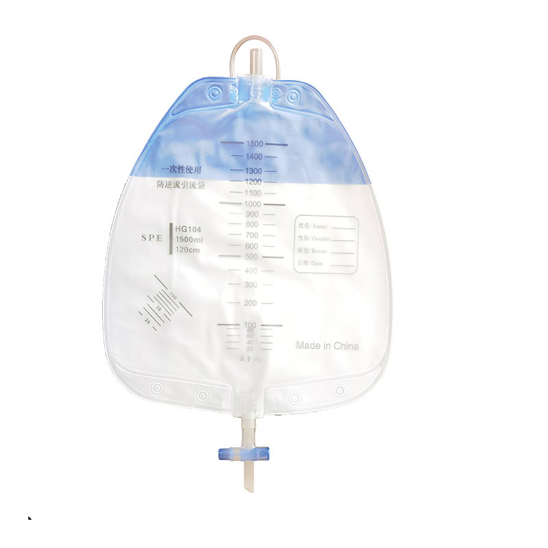
Liquid bags can be manufactured from different medical-grade film materials. Differences in thickness, flexibility, elasticity, and surface characteristics may affect how the material moves through the machine.
Flexible film can stretch or shift if feeding conditions are unstable. Excessive pulling force may change the relative position between the bag body and valve assembly area. Insufficient feeding control may also allow the material to move during the assembly cycle.
For this reason, the film feeding system should maintain consistent movement throughout bag forming, valve assembly, and welding.
Operators should also recheck machine settings when changing:
Film material
Film thickness
Bag dimensions
Valve type
Tube configuration
Production speed
Stable material handling provides the foundation for repeatable valve positioning.
A valve that is incorrectly positioned can create several production problems.
If the valve flange does not enter the intended welding area correctly, the welding pressure may not be distributed evenly. This can result in weak sealing areas or an unacceptable finished bag.
Misalignment may also cause interference with other components, including inlet tubes, outlet tubes, check films, or the bag edge.
In automatic production, repeated positioning errors can increase:
Rejected products
Material consumption
Machine adjustment time
Production interruptions
Manual inspection requirements
Therefore, valve positioning should be considered together with the entire bag manufacturing process rather than as an isolated assembly step.
Mechanical positioning is one of the most direct methods for controlling valve placement.
Dedicated guides, stops, fixtures, and assembly tooling define where the valve should be located during each production cycle. Once the machine has been correctly set up, these components provide a stable physical reference for repeated assembly.
The tooling should match the dimensions and shape of the specific valve being processed. This is particularly important for cross valves, pull valves, drainage valves, and other components with different flange structures.
Well-designed tooling can help:
Maintain consistent valve orientation
Limit unwanted lateral movement
Guide components into the assembly position
Reduce operator intervention
Improve repeatability during continuous production
Regular inspection of the tooling is also important because mechanical wear or loosening can gradually affect positioning accuracy.
For higher automation levels, valves can be supplied automatically to the assembly station.
A feeding mechanism organizes and transports the components into the required orientation before they enter the positioning fixture. The valve is then transferred or inserted into the appropriate position on the bag body.
This method reduces dependence on manual placement and supports continuous production.
For example, an automatic urine bag production line can integrate several operations, including:
Film feeding
Inlet tube feeding and welding
Check film processing
Discharge tube processing
Bag body welding
Valve feeding
Valve assembly
Integrating these processes into one coordinated production sequence helps maintain a more consistent relationship between the bag body and valve position.
Valve positioning also depends on the repeatability of the bag material itself.
Even when the valve feeding mechanism is correctly adjusted, unstable film movement can change the final assembly position. Film feeding should therefore remain consistent from one machine cycle to the next.
Important factors include:
Roller alignment
Film path stability
Feeding distance
Material tension
Surface friction
Production speed
When production materials are changed, trial production should be performed before returning the machine to normal operating speed.
This allows operators to verify that the bag body reaches the assembly station in the expected position.
Correct valve placement must be coordinated with the welding process.
The valve should reach and remain in its required assembly position before the welding operation begins. If the valve moves during welding or enters the welding area incorrectly, the resulting joint may not meet production requirements.
Liquid bag manufacturing equipment may use high-frequency welding to connect the bag body with tubes, ports, valves, or other components.
The positioning and welding stages therefore need to operate as one coordinated process.
A typical production sequence may include:
Film feeding
Tube or component feeding
Component positioning
Valve assembly
Bag body positioning
Welding
Finished-product discharge
Quality inspection
Stable timing between these operations helps improve both production efficiency and finished-product consistency.
A urine bag production line can include multiple components such as inlet tubes, outlet tubes, check films, cross valves, pull valves, and drainage components.
Each component requires a defined assembly position.
For production lines equipped with automatic valve assembly, valves can be supplied and assembled online according to the product configuration. This reduces manual operations and improves the continuity of the production process.
When changing to another urine bag specification, operators may need to adjust or replace the corresponding positioning tooling.
A drainage bag production line may use different valve designs, tube dimensions, or bag structures.
The positioning principle remains similar: each component needs to be mechanically guided into the required assembly position before welding or final assembly.
For manufacturers producing several bag types, modular tooling can make changeovers easier. Replaceable fixtures and adjustable machine settings allow the production line to accommodate different product formats without rebuilding the entire system.
Valve positioning should also be verified through finished-product quality control.
Rather than relying on visual recognition equipment, manufacturers can use appropriate process inspection and functional testing according to their quality requirements.
Inspection may include:
Checking valve orientation
Checking the relationship between the valve and welding area
Inspecting welded surfaces
Confirming valve assembly integrity
Checking the flow path
Performing bag leakage testing where required
For suitable production configurations, automatic bag leakage detection can also be integrated before the valve assembly process.
Performing leakage detection before final valve assembly can help prevent additional components from being installed on defective bags. This reduces unnecessary consumption of valve parts and avoids additional processing time.
Increasing production speed can improve output, but the valve feeding, bag feeding, positioning, assembly, and welding processes must remain synchronized.
If one mechanism operates too quickly relative to the other stations, the valve may not have sufficient time to enter or remain in its required position.
Higher production speed can also make mechanical instability more noticeable.
Manufacturers should therefore determine production speed based on the complete process rather than focusing only on the maximum cycle rate.
A stable production line usually provides better results than operating at a speed that causes frequent adjustments or rejects.
Production optimization should consider:
Valve feeding stability
Film feeding consistency
Assembly cycle time
Welding cycle time
Finished-product quality
Reject rate
Operator intervention frequency
Although automatic equipment reduces manual assembly, correct setup remains important.
Different bag and valve specifications may require changes to fixtures, feeding components, welding dies, or machine parameters.
Operators should follow standardized setup procedures when changing products.
Recommended checks include:
Confirm the correct valve and bag materials.
Install the corresponding valve positioning tooling.
Check valve feeding orientation.
Confirm film and tube feeding paths.
Adjust the required assembly position.
Check the relationship between the valve and welding tooling.
Run trial products.
Inspect positioning and sealing quality.
Begin continuous production only after the trial products meet requirements.
Standardized changeover procedures help reduce differences between operators and production shifts.
Mechanical positioning components require regular maintenance to maintain long-term repeatability.
Operators should periodically inspect:
Valve feeding tracks
Positioning fixtures
Mechanical stops
Clamping components
Pneumatic cylinders
Transfer mechanisms
Welding fixtures
Fasteners and mounting points
Accumulated contamination, loose components, or mechanical wear can gradually change the valve position.
Preventive maintenance therefore helps reduce unexpected positioning problems and production interruptions.
Valve positioning in liquid bag production can be controlled effectively through stable mechanical positioning, automatic valve feeding and assembly, controlled film movement, suitable tooling, and synchronization with the welding process.
Manufacturers evaluating a liquid bag making machine should focus on whether the equipment can maintain repeatable valve placement under actual production conditions.
Important considerations include:
Verify valve positioning with the actual bag film and valve components during machine testing.
Evaluate the stability of automatic valve feeding and assembly.
Check whether fixtures can be changed conveniently for different valve specifications.
Confirm that valve assembly and welding operations remain properly synchronized.
Establish standardized setup, inspection, and maintenance procedures.
Use appropriate leakage testing and finished-product inspection according to production requirements.
For urine bags, drainage bags, and other medical liquid bag products, reliable valve positioning is ultimately the result of coordinated mechanical design and stable process control.
A: Valve positioning can be controlled through mechanical guides, dedicated fixtures, automatic feeding mechanisms, and repeatable assembly movements. These components guide the valve into the required position before welding or final assembly.
A: Incorrect valve positioning can interfere with welding, affect the valve flow path, increase rejects, and reduce finished-product consistency. Stable positioning helps ensure that the valve and bag body enter the welding process in the correct relationship.
A: Yes. Depending on the production line configuration, valves can be automatically fed and assembled online. This reduces manual handling and supports continuous urine bag production.
A: Different valve types can be accommodated when the equipment is designed with suitable replaceable or adjustable feeding and positioning tooling. Changeover requirements depend on the valve structure, bag dimensions, and production configuration.
A: Film thickness, elasticity, friction, and flexibility can influence how the material moves through the production line. Stable film feeding is important because movement of the bag material can change the relative position of the valve assembly area.
A: The valve needs to reach the correct position and remain stable before welding begins. Proper synchronization helps prevent shifting during welding and supports consistent sealing.
A: Operators should run several trial products and check valve orientation, assembly position, welding alignment, and finished-product quality. If necessary, the positioning fixture or machine settings should be adjusted before continuous production begins.
